| 01 |
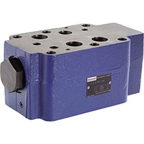
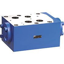
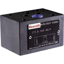
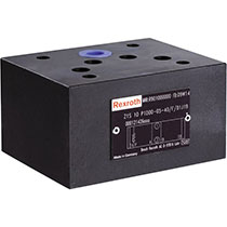
Check valve, sandwich plate |
Z1S |
| 02 |
Size 6 |
6 |
| Direction of flow |
|---|
| 03 |
Straight-through valve (in the channel) |
| A (A2 → A1) |
A |
| B (B2 → B1) |
B |
| A (A1 → A2) |
C |
| B (B1 → B2) |
D |
| A and B (A1 → A2) and (B1 → B2) |
E |
| P and T (P2 → P1) and (T1 → T2) |
F |
| P (P2 → P1) |
P |
| T (T1 → T2) |
T |
| Angle valve |
| B → A |
B-A |
| T → P |
T-P |
| AB → P |
AB-P |
| Symbols see circuit diagrams |
| Cracking pressure |
|---|
| 04 |
0,5 bar |
5 |
| 1,5 bar |
15 |
| 3,0 bar |
30 |
| 5,0 bar |
50 |
| 05 |
Component series 40 … 49 (40 … 49: unchanged installation and mounting dimensions) |
4X |
| Seal material |
|---|
| 06 |
FKM seals |
V |
| Observe compatibility of seals with hydraulic fluid used. (Other seals upon request) |
| Corrosion resistance (outside; thick film passivated according to DIN 50979 Fe//Zn8//Cn//T0) |
|---|
| 07 |
None (valve housing primed) |
no code |
| Improved corrosion protection (240 h salt spray test according to EN ISO 9227) |
J3 |
| 08 |
Without locating hole |
no code |
| With locating hole |
/601) |
| With locating hole and locking pin ISO 8752-3x8-St |
/62 |
| Special version |
|---|
| 09 |
Standard version |
no code |
| Measuring port in P (G1/4; on channel B side) |
SO68 |
| Measuring port in P (G1/4; on channel A side) |
SO118 |
| Measuring ports A and B (G¼) |
SO90 |
| Measuring port T (G¼) |
SO2 |
| Direction of flow P1 → P2 (opposite to version “P”) |
SO104 |
| See symbols (examples) |
| 10 |
Further details in the plain text |
* |




 Your Lift