Hiwin Shaft Motors - LMTA series
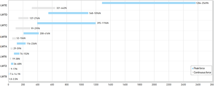
The HIWIN LMTA series: LMTA = Diameter of stator = 20mm, Peak = 116N - 236N, Continuous = 29N - 59N
Linear Shaft Motors - LMTA series
The HIWIN rod-shaped linear motor has a variety of size series, with complete specifications, and easy installation. The maximum peak force for this motor is up to about 2570N. It complies with international safety CE certification, has dustproof and a waterprood IP66 rating. Using direct drive technology, on other mechanical conversion components arr needed to acieve linear tranmission, with high-speed, no cogging and low velocity ripple along with other characteristics including; excellent dynamic performance, no wear, zero backlash, and easy maintenance. Compared to traditional mechanical linear solutions, the motor effectively enhances machine equipment production capacity and reduces maintenance costs to meet the needs of high-precision positioning control and smooth operation applications such as high-speed light-load automation equipment, dust-free environment, automation equipment, panel equipment, optical inspection equipment, tool line cutting equipment, scanning electron microscope equipment, medical automation and other industries.
ดาวน์โหลดไฟล์ PDF
Feature | Shaft Motors - LMTA series
- Excellent dynamic characteristics : no cogging
- Low velocity ripple
- Max. Acceleration up to 5G
- CE certification
- Ingress Protection rating : IP66
- No wear, zero backlash
- Similar to screw mechanism, easy to install
Force Chart | Shaft Motors - LMTA series

Code | Shaft Motors - LMTA series

Specifications | Shaft Motors - LMTA series
| Detail | Symbol | Unit | LMTA2 | LMTA3 | LMTA4 |
|---|---|---|---|---|---|
| Continuous force | Fc | N | 29 | 45 | 59 |
| Continuous current | Ic | Arms | 1.6 | ||
| Peak force (1s) | Fp | N | 116 | 180 | 236 |
| Peak current (1s) | Ip | Arms | 6.4 | ||
| Force constant | Kf | N/Arms | 18 | 28 | 37 |
| Electrical time constant | Ke | ms | 0.7 | ||
| Resistance (line to line 25°C) | R25 | Ω | 7.4 | 11.1 | 14.8 |
| Inductance (line to line) | L | mH | 5.0 | 7.5 | 10.0 |
| Pole pair pitch | 2T | mm | 72 | ||
| Minimum beanding radius of cable | Rbend | mm | 37.5 | ||
| Back emf constant (line to line) | Kv | Vrms/(m/s) | 11.7 | 17.5 | 23.3 |
| Motor constant ( 25°C) | Km | N/√W | 5.4 | 6.9 | 7.9 |
| Thermal resistance | RTH | °C/W | 2.4 | 1.6 | 1.2 |
| Thermal switch | - | - | PTC | ||
| Maximum DC bus voltage | - | VDC | 325 | ||
| Mass of forcer | Mf | kg | 0.45 | 0.63 | 0.80 |
| Unit mass of stator | Ms | kg/m | 2 | ||
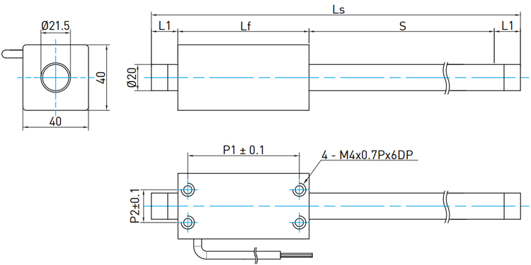
| Length of forcer | Lf | mm | 94 | 130 | 166 |
| Mounting pitch | P1 x P2 | mm | 84 x 20 | 120 x 20 | 156 x 20 |
| Stroke | S | mm | 100 ~ 1550 (Take 50 mm as increase unit) | ||
| Clamping length | L1 | mm | 25 (Stroke = 100 ~ 300 mm) 40 (Stroke = 350 ~ 700 mm) 60 (Stroke = 750 ~ 1550 mm) |
||
| Total stator length | Ls | mm | Ls (Total stator length) = S (Stroke) + Lf (Length of forcer) + 2*L1 (Clamping legnth) | ||
- Values in the table refer to operation without forced cooling.
- Except diemensions, the electrical specifications are in ±10% of tolerance.
- We reserve the right of changes, please follow customer recognition drawings.


 Your Lift