
Hydraulic cylinder รุ่น CDT3...Z-3X
Hydraulic cylinder tie rod design
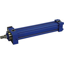
รายละเอียด Hydraulic cylinder รุ่น CDT3...Z-3X
- Series T3
(รุ่น T3) - Component series 3X
(ใช่ร่วมกับรุ่น 3X) - Nominal pressure 160 bar
(แรงดันปกติ 160 บาร์) - Piston Ø 25 … 200 mm
(ขนาดลูกสูบ 25 - 200) - Piston rod Ø 12 … 140 mm
(ก้านลูกสูบ 12 - 140)
Features
- Installation dimension acc. to ISO 6020/2, DIN 24554 and NF/ISO 6020/2
(ขนาดการติดตั้งมาตรฐาน ISO 6020/2, DIN 24554 และ NF/ISO 6020/2) - 13 types of mounting
(มีการติดตั้ง 13 แบบ) - Integrated guide socket for fast and easy maintenance
(เป็นแบบเต้ารับเพื่อรวดเร็วต่อการติดตั้งและซ่อมบำรุ่ง) - Optional self-adjusting or adjustable end position cushioning
(ปรับกันกระแทกได้ด้วยตัวเองหรือตั่งค่าเองก็ได้)
SPECIFICATION (รายละเอียด)
| แรงดันปกติ | bar | 160 |
|---|---|---|
| แรงดันใช้งานขั้นต่ำ (ไม่มีภาระ) | bar | 10 |
| แรงดันใช้งานสูงสุด (เมื่อมีภาระ) | bar | 210 |
| แรงดันทดสอบเฉลี่ย | bar | 240 |
| ลดแรงกดดันในการทดสอบ | mm²/s | 2,8 … 380 |
| ความหนืดเหมาะสมที่อุณหภูมิใช้งาน | mm²/s | 20 … 100 |
| ระดับการปนเปื้อนของน้ำมันไฮดรอลิกสูงสุดที่ยอมรับได้ระดับความสะอาดตาม ISO 4406 (c) | Class 20/18/15 ตามมาตรฐาน ISO 4406 (c) | |
| Bleeding | By default | |
Type code
| 01 | 02 | 03 | 04 | 05 | 06 | 07 | 08 | 09 | 10 | 11 | 12 | 13 | 14 | 15 | 16 | 17 | 18 | |||
|---|---|---|---|---|---|---|---|---|---|---|---|---|---|---|---|---|---|---|---|---|
| CD | T3 | / | / | / | Z | 3X | * |
| 01 | Single rod cylinder | CD | |
| 02 | Series | T3 | |
| Types of mounting | |||
|---|---|---|---|
| 03 | Types of mounting DIN/ISO | Rectangular flange at cylinder head | ME5 |
| Rectangular flange at cylinder base | ME6 | ||
| Self-aligning clevis at cylinder base | MP5 | ||
| Foot mounting | MS2 | ||
| Trunnion in center | MT4 1) | ||
| Types of mounting ISO | Fork at cylinder base | MP1 | |
| Swivel eye at cylinder base | MP3 | ||
| Trunnion at cylinder head | MT1 | ||
| Trunnion at cylinder base | MT2 | ||
| Extended tie rod, on both sides | MX1 | ||
| Extended tie rod at cylinder base | MX2 | ||
| Extended tie rod at cylinder head | MX3 | ||
| Tapped hole at cylinder head | MX5 2) | ||
| 04 | Piston Ø (ØAL) 25 … 200 mm | ... | |
| 05 | Piston rod Ø (ØMM) 12 … 140 mm13) | ... | |
| 06 | Stroke length in mm11) | ... | |
| Design principle | |||
| 07 | Cylinder head and cylinder base connected by tie rod | Z | |
| Component series | |||
| 08 | Component series 30 … 39 (30 … 39: unchanged installation and connection dimensions) | 3X | |
| Line connection / version | |||
| 09 | Pipe thread according to ISO 1179-1 | B | |
| Metric ISO thread (ISO 6149-1) | R 17) | ||
| Enlarged pipe thread (ISO 1179-1) | S | ||
| Line connection/position at cylinder head | |||
| 10 | View to piston rod |  |
1 |
| 2 | |||
| 3 | |||
| 4 | |||
| Line connection/position at cylinder base | |||
| 11 | View to piston rod |  |
1 |
| 2 | |||
| 3 | |||
| 4 | |||
| Piston rod design | |||
| 12 | Hardened and hard chromium-plated | H | |
| Piston rod end | |||
| 13 | Thread (DIN/ISO) for swivel head CGKA | H 14) | |
| Thread (ISO) for swivel head CGKA | D 15) | ||
| Internal thread | E 12) | ||
| With mounted swivel head CGKA (DIN/ISO) | F 5; 14) | ||
| With mounted swivel head CGKA (ISO) | K 5; 15) | ||
| With trunnion | T 6) | ||
| End position cushioning | |||
| 14 | Without end position cushioning | U | |
| Both sides, self-adjusting | D | ||
| Head sides, self-adjusting | S | ||
| Base sides, self-adjusting | K | ||
| Both sides, adjustable | E 4) | ||
| Seal design | |||
| 15 | Standard seal system | M | |
| Reduced friction | T | ||
| High temperature with reduced friction | S | ||
| Option 1 | |||
| 16 | Without option | W | |
| Leakage oil connection | B 3; 4; 16) | ||
| Threaded coupling, on both sides | A | ||
| Option 2 | |||
| 17 | Without option | W | |
| Piston rod extension “LY”, specify in mmin plain text | Y | ||
| 18 | Further details in the plain text | ... | |
- 1) Trunnion position freely selectable. When ordering, always specify the "XV" dimensions in the plain text in mm
- 2) Not ISO-standardized
- 3) For type of mounting MS2 and piston Ø 25 mm and end position cushioning “E” not possible
- 4) With piston Ø 25 … 100 mm: only line connection “B” possible.
With piston Ø 125 … 200 mm: only DIN type of mounting and line connection “B” possible. - 5) Not possible with type of mounting Mx1 and MX3
- 6) See dimensions - piston rod ends E and T (only possible with standardized piston rod Ø 22 … 140 mm, observe max. operating pressure.
- 11) For max. available stroke length, see technical data, and for admissible stroke length (according to the kinking calculation), see project planning information.
- 12) See dimensions - piston rod ends E and T (only possible with standardized piston rod Ø 18 … 140 mm, observe max. operating pressure.
- 13) Observe the admissible piston rod Ø and assigned threads at the piston rod end for 210 bar (see technical data and dimensions)
- 14) For operating pressure up to 160 bar
- 15) For operating pressure up to 210 bar
- 16) Not possible with MT1
- 17) For type of mounting ME5 and ME6, only position 1 and 3 possible
Order examples:
CDT3MP5/50/36/300Z3X/B11HHDMWW
Please observe the relevant restrictions when selecting!
Data Sheet : Hydraulic cylinder รุ่น CDT3...Z-3X


 Your Lift