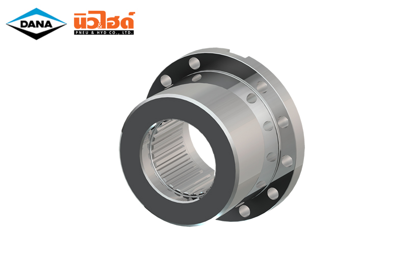
DANA Companion Flanges
DANA Companion Flanges

Feature | DANA Companion Flanges
Standard companion flanges can be manufactured with cylindrical bore holes and face keyway (material C45; hardened and tempered 750 – 900 N/ mm2) on request. For designs deviating from the standard, e.g., oil pressure connection, conical bore, flat journal, and material, relevant drawings are required.
Face Key connection series 687/688/587/390
The driveshaft for series 687/688/587/390 can also be manufactured with face key connection on request.
Specifications | DANA Companion Flanges
ตารางสเปค Hirth-Serration (Specification Hirth-Serration)
Hirth-Serration
- Flank angle 40°
- High transmission capacity
- Form locking
- Self-centering
| D mm | d mm | z | B mm | i* |
|---|---|---|---|---|
| 225 | 180 | 48 | 200 | 2 x M 12 |
| 250 | 200 | 48 | 225 | 8 x M 14 |
| 285 | 225 | 60 | 255 | 10 x M 14 |
| 315 | 250 | 60 | 280 | 10 x M 16 |
| 350 | 280 | 72 | 315 | 12 x M 16 |
| 390 | 315 | 72 | 350 | 12 x M 18 |
| 435 | 345 | 96 | 395 | 16 x M 18 |
| 480 | 370 | 96 | 445 | 16 x M 20 |
| 550 | 440 | 96 | 510 | 16 x M 22 |
| 600 | 480 | 120 | 555 | 20 x M 24 |
| 650 | 520 | 120 | 605 | 20 x M 24 |
| 700 | 570 | 120 | 655 | 24 x M 24 |
| 750 | 600 | 144 | 695 | 24 x M 30 |
| 800 | 650 | 144 | 745 | 24 x M 30 |
| 850 | 680 | 144 | 785 | 24 x M 36 |
| 900 | 710 | 144 | 835 | 24 x M 36 |
| 950 | 760 | 144 | 885 | 24 x M 36 |
| 1,000 | 800 | 180 | 925 | 20 x M 42 x 3 |
| 1,050 | 840 | 180 | 975 | 20 x M 42 x 3 |
| 1,100 | 880 | 180 | 1,025 | 20 x M 42 x 3 |
| 1,150 | 925 | 180 | 1,065 | 20 x M 48 x 3 |
| 1,200 | 960 | 180 | 1,115 | 20 x M 48 x 3 |
ตารางสเปค Klingelnberg-serration (Specification Klingelnberg-serration)
Klingelnberg-Serration
- Flank angle 25°
- High transmission capacity
- Form locking
- Self-centering
| D mm | d mm | z | B mm | i* |
|---|---|---|---|---|
| 95 | 65 | 16 | 84 | 4 x M 8 |
| 115 | 80 | 24 | 101.5 | 4 x M 10 |
| 145 | 110 | 24 | 130 | 4 x M 12 |
| 175 | 140 | 32 | 155.5 | 4 x M 16 |
| 215 | 175 | 48 | 196 | 4 x M 16 |
| 240 | 195 | 48 | 218 | 4 x M 18 |
| 275 | 220 | 48 | 245 | 4 x M 20 |
| 305 | 245 | 48 | 280 | 4 x M 20 |
| 340 | 280 | 72 | 310 | 4 x M 22 |
| 380 | 315 | 72 | 345 | 6 x M 24 |
| 425 | 355 | 96 | 385 | 6 x M 27 |
| 465 | 390 | 96 | 425 | 8 x M 30 |
| 535 | 455 | 96 | 492 | 8 x M 30 |
- D = Outside diameter
- d = Inside diameter
- Z = Number of teeth
- B = Pitch diameter
- i = Number and size of bolts Bolt mater: 10.9
- * Reduced number of bolts by special arrangement only (e.g., for use as quick-change system)


 Your Lift